


Categories


Latest Products


Electric Imp April - Breakout Development Board
- Product SKU: SS_109990043
- Category: Accessories, Communication, Development Platform, IoT, Wireless

- Order within
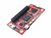
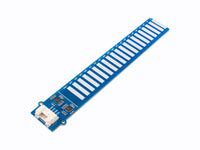
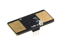
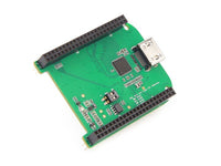
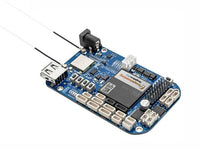
April is a very simple breakout board with the minimum required components for an imp001 device.
Power
Power can be supplied using a USB Mini-B cable from a USB Charger or a standard USB Port, though the data lines are not connected to anything. Optionally, a battery connector can be soldered to the battery pads P+ and P-. April can operate from any DC voltage from 3.3V to 17V, and tolerates voltages down to -12V. This is helpful for any application with removable batteries where they may be inserted backwards by the user. You may select between USB power and battery power by placing a shunt on the power select header. Please note that April does not have any circuitry for charging a battery and you should never short USB power to the battery pack.
April uses the TI TPS62172 DC/DC Buck Power supply for 3.3V. It can provide an additional 100mA@3V3 to any boards connected to April. However, if your application requires more than 100mA@3V3, it must have its own supply.
The three-pin jumper allows selection of the DC input source: the jumper between the middle pin and the side labeled USB for USB power, and the other way for battery pack power (soldering the input leads onto the P+ and P- pads).
Signals
All of the signals from the imp come out to a header. For descriptions of pin of function see the Imp Pin Mux.
Card Detect
If your application requires the card detect signal, it must be pulled up by soldering an 0402 resistor R3 or on an external board. The signal is connected to GND whenever a card is present in the slot, so we recommend using a 100k¦Ø or higher resistor to save power.
Vin
This pad is connected to the input voltage being fed to the board - either the USB 5V supply or the reverse-voltage protected battery pads.
Resources
Schematics
Gerber Files
Bill of Materials
Altium Source Files
Any further questions, please view the Electric Imp forum.
Technical details
Dimensions 100mm x57mm x5mm
Weight G.W 10g
Battery Exclude
RETURNS POLICY
Lorem ipsum dolor sit amet, consectetur adipiscing elit. Morbi ut blandit risus. Donec mollis nec tellus et rutrum. Orci varius natoque penatibus et magnis dis parturient montes, nascetur ridiculus mus. Ut consequat quam a purus faucibus scelerisque. Mauris ac dui ante. Pellentesque congue porttitor tempus. Donec sodales dapibus urna sed dictum. Duis congue posuere libero, a aliquam est porta quis.
Donec ullamcorper magna enim, vitae fermentum turpis elementum quis. Interdum et malesuada fames ac ante ipsum primis in faucibus.
Curabitur vel sem mi. Proin in lobortis ipsum. Aliquam rutrum tempor ex ac rutrum. Maecenas nunc nulla, placerat at eleifend in, viverra etos sem. Nam sagittis lacus metus, dignissim blandit magna euismod eget. Suspendisse a nisl lacus. Phasellus eget augue tincidunt, sollicitudin lectus sed, convallis desto. Pellentesque vitae dui lacinia, venenatis erat sit amet, fringilla felis. Nullam maximus nisi nec mi facilisis.
SHIPPING
Lorem ipsum dolor sit amet, consectetur adipiscing elit. Morbi ut blandit risus. Donec mollis nec tellus et rutrum. Orci varius natoque penatibus et magnis dis parturient montes, nascetur ridiculus mus. Ut consequat quam a purus faucibus scelerisque. Mauris ac dui ante. Pellentesque congue porttitor tempus. Donec sodales dapibus urna sed dictum. Duis congue posuere libero, a aliquam est porta quis.
Donec ullamcorper magna enim, vitae fermentum turpis elementum quis. Interdum et malesuada fames ac ante ipsum primis in faucibus.
Curabitur vel sem mi. Proin in lobortis ipsum. Aliquam rutrum tempor ex ac rutrum. Maecenas nunc nulla, placerat at eleifend in, viverra etos sem. Nam sagittis lacus metus, dignissim blandit magna euismod eget. Suspendisse a nisl lacus. Phasellus eget augue tincidunt, sollicitudin lectus sed, convallis desto. Pellentesque vitae dui lacinia, venenatis erat sit amet, fringilla felis. Nullam maximus nisi nec mi facilisis.